
Silicone Mold Making is a chain of design, material, process, and acceptance decisions. It is not simply the act of pouring liquid silicone over a master. An unresolved detail at the start can return later as a weak wall, trapped air, visible seam, difficult release, or poor assembly fit.
A controlled project starts with the finished casting requirement. It then moves through design input, mold structure, master preparation, material selection, processing, demolding, and first-cast approval. The practical goal is to keep one approved geometry, one defined casting process, and one acceptance method connected from the first review to the finished mold.
Step 1 Define the Casting Requirement
The mold should be designed around the finished cast, not around a file alone. Accordingly, the initial brief should state the casting material, overall size, critical details, undercuts, intended production pattern, and contact requirements.
The casting compound affects filling, heat exposure, cure behavior, weight, adhesion, and release. Wax, resin, soap, gypsum, concrete, food mixtures, and other materials do not behave in the same way. Therefore, the intended compound and working method should be confirmed before silicone selection.
Dimensions also need priorities. Overall size may be less important than a mating face, insert position, hole location, or sealing area. Meanwhile, visible surfaces, texture, lettering, and logos need clear cosmetic expectations.
Deep undercuts, narrow ribs, enclosed areas, and sharp projections can trap air or create weak silicone zones. These features may require a split structure, removable insert, revised parting line, or different demolding direction. As a result, geometry should be reviewed before the master is finalized.
Contact requirements belong in the same brief. Evidence for food-contact, skin-contact, or regulated industrial use depends on the selected formulation and market. Current TDS, SDS, available records, or a relevant sample test should support the final decision.
Requirement record
- Casting material and processing method
- Overall size, critical dimensions, and assembly interfaces
- Visible surfaces, texture, lettering, and logo details
- Undercuts, thin sections, inserts, and fragile features
- Expected casting frequency, cleaning, and storage method
- Contact, documentation, inspection, and approval needs
Step 2 Prepare the Design Input
Each design input supports different decisions. A file can show the shape clearly while still omitting units, tolerance, surface intent, or revision history. Therefore, the project package should identify one approved source of dimensional truth.
STEP files usually support editable solid geometry and engineering review. STL files describe a triangulated surface and are often used for printing or visualization. An STL can still be suitable, although major geometry changes may require remodeling rather than simple editing.
Drawings can define datums, tolerances, holes, and assembly relationships. Photographs help explain orientation and appearance, yet perspective prevents dependable measurement. A physical sample can support reverse engineering, but wear, damage, deformation, and missing features must be identified before copying begins.
Version control prevents the master from following one file while comments refer to another. Each package should therefore show the file name, revision, date, unit system, overall dimensions, and approval status.
| Input | Best used for | Confirm before approval | Main risk |
|---|---|---|---|
| STEP file | Editable geometry and dimensional review | Units, revision, and critical features | An older revision may look complete |
| STL file | Surface shape and printed masters | Scale, mesh quality, and edit scope | Faceting, holes, or limited editability |
| 2D drawing | Tolerances, datums, and interfaces | View consistency and revision | Hidden geometry may remain unclear |
| Physical sample | Reverse engineering and shape recovery | Condition, measurement, and repairs | Wear or damage may be copied |
Practical control: supporting photographs, sketches, and samples can explain appearance or use. They should not create competing dimensions or unapproved geometry.
If the project still needs to decide which source should control the geometry, use the dedicated guide to STL, STEP and physical-sample input. For this workflow, the important point is simpler: one approved source must control scale, critical dimensions, surface intent, and revision status before master production begins.
Step 3 Review Mold Structure
Mold structure turns product geometry into a workable casting method. The review should explain how material enters, how air escapes, how the cast releases, and how the cavity keeps its intended shape. Visual accuracy alone is not enough.
Demolding direction matters because each undercut resists release in a specific direction. A simple open-face form may lift directly from the cavity. Enclosed shapes, crossing features, rigid inserts, or deep recesses can instead require split or multi-part construction.
The parting line affects appearance, trimming, alignment, and leakage. A seam across a visible face may add finishing work, while a hidden seam can protect the presentation surface. However, the least visible position is not always the safest release path.
Thin walls, narrow bridges, deep slots, and sharp projections create stress zones. Large or highly flexible molds may also need a support shell to hold the intended geometry during filling and handling. That support must still allow reliable opening, alignment, and cleaning.
Finally, the structure needs enough operating space. Clamps, inserts, fasteners, tools, pouring containers, and hands all need access. A technically removable cast can still be impractical when no safe grip or opening sequence exists.
Structure review questions
- Which direction releases the cast with the least stress?
- Where can the parting line sit without harming critical surfaces?
- How many mold sections are necessary?
- Which areas may tear, trap air, or distort?
- Is a support shell required?
- Is there enough room for filling, venting, opening, and trimming?
Large, deep, heavy, or strongly undercut parts may need a more detailed review of support, parting line and demolding design. This step only needs enough structural detail to prove that filling, opening, alignment, and release can work before the master is committed.
Step 4 Create and Finish the Master Pattern
The master defines the cavity surface, so scratches, print layers, seams, dust, dents, and repairs can transfer into the finished mold. It should therefore be treated as a production reference rather than a rough visual prototype.
3D printed masters may need sanding, filling, sealing, coating, or polishing. CNC masters can also show tool paths, fixture marks, or inaccessible internal corners. In both cases, the approved finish should match the intended cast surface.
An existing object can serve as a master, but porous materials, loose paint, oils, moisture, flexible coatings, and fragile details require review. Sealing may create a more controlled surface, although the sealer can also soften edges or fill fine detail.
For that reason, uncertain coatings and master materials should receive a small compatibility test. Repairs should also be photographed and approved, so later inspection compares the mold with the final master rather than an older model.
Master approval points
- Critical dimensions match the approved input
- Surface finish reflects the intended cast
- Print lines, seams, repairs, and tool marks are controlled
- Porous or reactive areas are handled appropriately
- The master is stable in the planned orientation
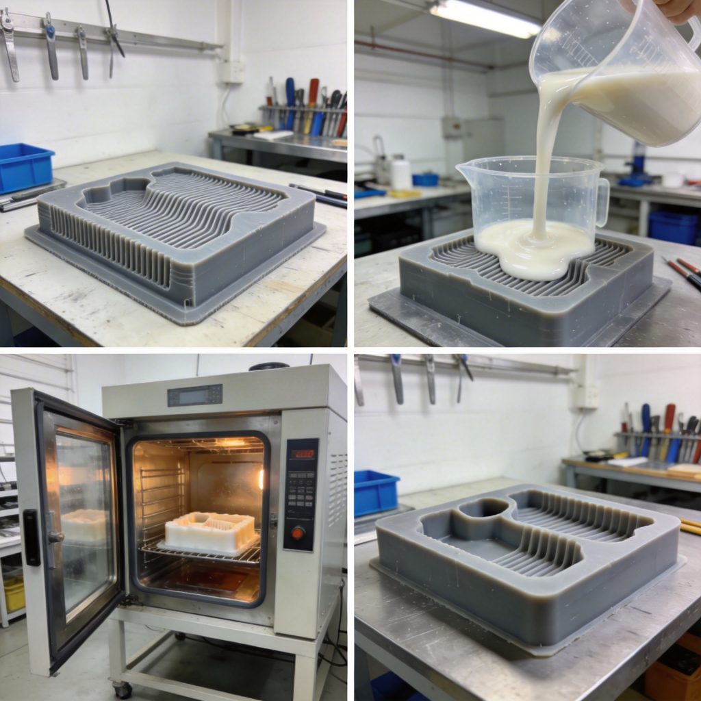
Step 5 Select Silicone and Process Conditions
Silicone selection should follow both geometry and casting conditions. Cure system, hardness, viscosity, tear behavior, flexibility, compatibility, and dimensional needs work together. Selecting one attractive property cannot correct a poor mold structure.
Hardness affects support and flex. A softer system may release difficult undercuts more easily but can need stronger external support. A firmer system may hold shape better while placing more stress on delicate casting features.
Viscosity influences flow around details and narrow spaces. However, actual behavior also depends on working time, temperature, mixing, and cavity orientation. Published TDS guidance should therefore replace general assumptions.
Compatibility needs direct attention because master materials, coatings, release agents, pigments, cleaners, and casting compounds can affect cure or surface quality. When the combination is uncertain, a small sample can reveal inhibition, adhesion, or incomplete cure before the full pour.
Mix ratio, working time, cure schedule, post-cure needs, and environmental limits vary by formulation. The production plan should use current documents for the exact material and record any project-specific test results.
When hardness, viscosity, or tear resistance is still an open decision, review those properties separately in the silicone for mold making material guide. The mold-making workflow should not select a grade from one number alone; it should identify the failure risk that the material and structure must prevent together.
Trade-offs that should be resolved before production
| Conflict | What usually looks attractive | What must also be protected | Practical decision |
|---|---|---|---|
| Hidden seam vs safe release | Move the parting line completely away from a visible face | Opening access, flange space, fragile details, and repeatable alignment | Accept the least harmful visible seam when a fully hidden line would create a locked or unstable opening sequence |
| Soft release vs dimensional stability | Choose a very soft silicone for difficult undercuts | Wall position, filled shape, and support during curing | Use flexibility where release needs it and add wall thickness or external support where the cavity must stay fixed |
| Low viscosity vs process control | Use the most fluid material for fine details | Leakage control, working time, vertical retention, and complete mixing | Choose workable flow for the real cavity and verify it with the actual pour direction and batch size |
| Fast approval vs representative testing | Approve from an easy substitute casting material | Real heat, weight, flow, release, fit, and surface conditions | Use the intended compound whenever practical, or document exactly which risks the substitute cannot validate |
Step 6 Build the Mold Box and Plan Pouring
The mold box controls boundaries, master position, wall thickness, and working access. It must resist leakage and movement during filling. Even a small gap can release material, while a shifting master can change the cavity position.
Spacing should reflect geometry and expected flexing rather than visual symmetry. A feature placed too close to the box can leave a weak outer wall. Joints, supports, inserts, and parting surfaces also need secure sealing without covering approved detail.
Registration keys help split sections return to the same position. Poorly shaped keys can lock sections together, while weak registration can permit offset or leakage. Their depth, spacing, and release direction should be planned with the parting line.
Pouring direction should help material rise around the master while air moves toward planned vents. Complex cavities may need feed points, brushing, staged application, or another proven method. Vents should serve identified high points rather than appear as random openings.
Material quantity depends on box volume, master displacement, mold wall design, processing losses, and the selected method. Consequently, the calculation should use confirmed dimensions instead of an invented universal formula.
Pre-pour readiness check
- The box is stable, sealed, and accessible
- Master orientation matches the approved structure
- Critical areas retain adequate mold wall space
- Keys, inserts, and supports are secured
- Feed and vent paths remain open
- Material quantity has a documented basis
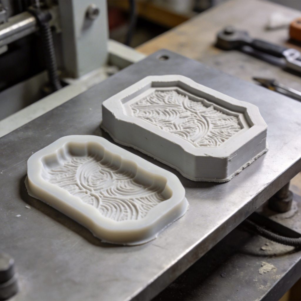
Step 7 Mix, Pour and Cure
Processing starts with positive identification of both components. Labels, lot numbers, container condition, and document revision should be checked before measurement. Clean, compatible tools also reduce avoidable contamination.
The stated mix ratio and measurement method must be followed. A weight ratio should not be casually converted into a volume ratio. Small batches also need a scale or measuring system with suitable resolution.
Mixing should reach the container walls and bottom without leaving streaks. At the same time, unnecessary agitation can introduce more air. The method should balance complete blending with controlled bubble generation.
Bubble management depends on the selected formulation, equipment, and cavity geometry. Vacuum treatment, careful pouring, brushing, pressure processing, or staged application may suit different conditions. The chosen approach should follow the TDS and a verified workshop method.
A steady pour through the planned entry point helps the material follow the reviewed filling path. Environmental conditions should also remain stable because dust, moisture, temperature changes, vibration, and nearby contaminants can affect the result.
Cure timing must follow guidance for the exact material and actual conditions. Early opening can damage weak areas. Extra waiting time, however, cannot correct an inaccurate ratio, incomplete mixing, or contamination.
Batch record
- Material identity, lot number, and TDS revision
- Batch size, ratio, and measurement equipment
- Mixing and bubble-control method
- Pouring and cure times
- Relevant environmental observations
- Leakage, movement, contamination, or surface changes
Step 8 Demold and Finish
Demolding should follow a planned sequence rather than maximum pulling force. Box panels, supports, parting surfaces, inserts, and the master should release in a controlled order. Slow flexing is safer than using sharp tools near the cavity.
The master should leave in the approved direction. Unexpected twisting, stretching, or cutting should be recorded because it may reveal a structural problem. Split sections should also close again without steps, gaps, or alignment changes.
Trimming removes flash, vent tails, feed extensions, and unwanted edges. However, cutting too close can weaken the cavity boundary or alter the parting fit. Registration features, sealing faces, and support contact areas must remain intact.
Initial inspection should identify tears, tacky areas, uncured zones, trapped bubbles, thin spots, and unintended marks. Photographs of the cavity, outer surfaces, parting faces, and repairs create a baseline for first-cast testing.
Step 9 First-Cast Testing and Acceptance
A first cast converts design assumptions into observable results. Whenever practical, the test should use the intended casting compound or a technically relevant alternative. A convenient substitute may not represent actual flow, heat, release, or surface behavior.
Acceptance points should be defined before the test begins. Otherwise, different reviewers may judge the same casting by appearance alone. Critical defects should be separated from correctable trimming or process adjustments.
Surface inspection checks texture transfer, bubbles, contamination, seam marks, and missing detail. The record should distinguish a cavity defect from a mixing, venting, filling, or casting-material issue.
Dimensional inspection should focus on approved control points. Interfaces, holes, inserts, mating faces, and assembly locations often matter more than one overall measurement. The inspection method should match the drawing and acceptance plan.
Leakage should be mapped to the exact parting line, plug, insert, or feed connection. Deformation should be observed before filling, during filling, and after release. Fixed-angle photographs can make those changes easier to compare.
Demolding records should note the release sequence, flexing zones, tool use, and risk to delicate features. Assembly testing should then confirm fit, alignment, contact, sealing, or other required functions. A visually attractive first cast cannot replace those checks.
First-cast acceptance points
- Surface transfer, bubbles, seams, and missing detail
- Critical dimensions, holes, interfaces, and inserts
- Leakage around joints, plugs, and feed points
- Deformation during filling and after release
- Demolding sequence and stress on fragile features
- Assembly fit and required functional checks
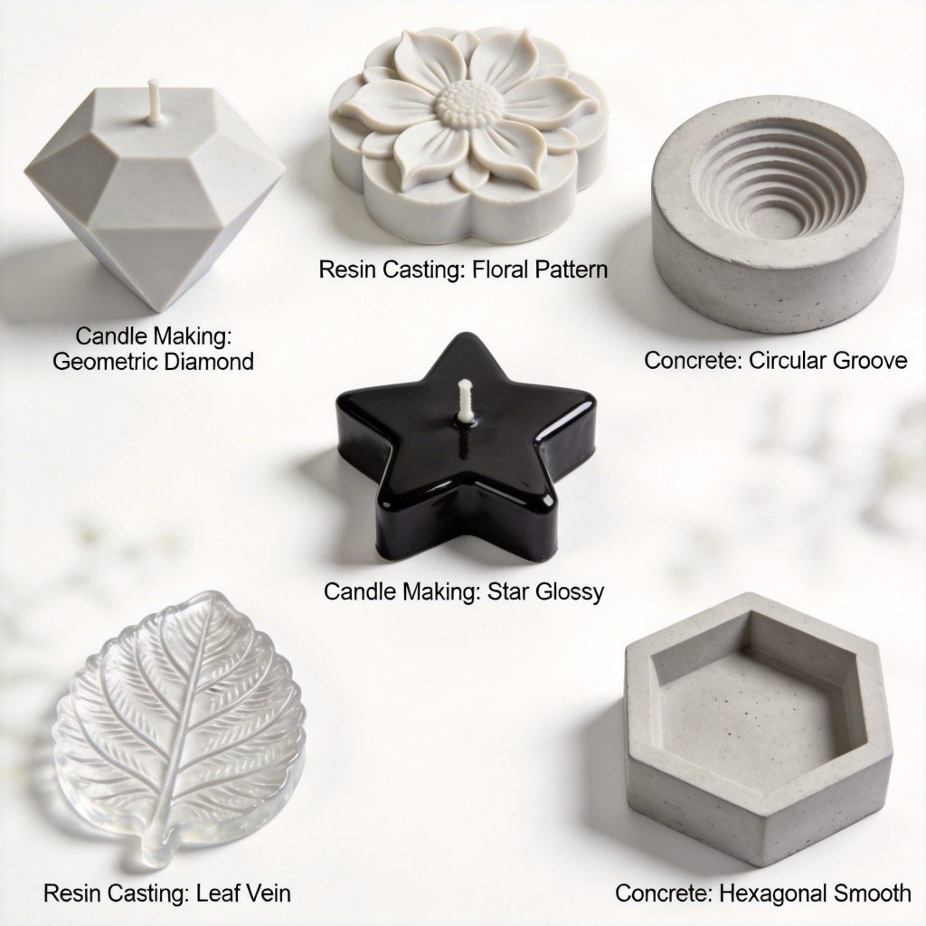
Approval should create a clear record rather than a vague pass or fail. A minor vent tail may be accepted with a defined trimming method, while a critical dimensional error requires design action. When major changes occur, the next sample should identify which earlier results remain valid.
Custom Project or Ready-Made Mold?
The correct route depends on geometry, design ownership, fit, release, and approval needs. A custom route suits a defined project, while a catalog mold can be efficient when an existing shape already meets the application.
The decision should also consider modification, finishing, casting fit, and verification work. The lowest initial purchase amount does not always create the simplest production route.

Custom Mold Development
This route supports exclusive geometry, controlled dimensions, unusual undercuts, branded details, inserts, and application-specific structures.
Best fit: exclusive collections, controlled interfaces, branded shapes, complex release structures, and prototype casting work.
- The shape contains exclusive or protected details
- Dimensions must match another component
- Undercuts, inserts, or seams need structural review
- Acceptance requires measurements or functional checks
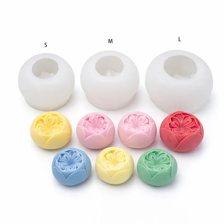
Ready-Made Silicone Molds
This route can suit common decorative forms, familiar craft shapes, routine soap formats, or an established casting requirement.
Best fit: standard shapes, common casting formats, sample ranges, and applications without structural customization.
- No exclusive geometry or controlled interface is required
- An existing shape fits the intended casting format
- Minor variation will not affect assembly or branding
- Direct selection matters more than design revision
Project Handoff Gates: What Must Be Frozen Before the Next Stage
A strong project file does more than collect checklists. It shows which decisions are frozen, who can reopen them, and what evidence is required before the next stage starts. This prevents a late comment about material, geometry, or surface finish from quietly invalidating work that has already been approved.
Gate 1: Design input released
- Freeze: controlling revision, units, critical dimensions, visible surfaces, and intended casting compound
- Release when: conflicting drawings, screenshots, or samples have been reconciled
- Reopen if: geometry, scale, interface dimensions, or casting material changes
Gate 2: Mold structure approved
- Freeze: section count, parting line, release direction, support concept, feed and vent strategy
- Release when: every section has an opening direction, grip area, and reassembly method
- Reopen if: a fragile detail, locked undercut, restricted seam area, or handling limit appears
Gate 3: Master and process released
- Freeze: final master condition, repairs, surface finish, silicone reference, ratio, and cure method
- Release when: compatibility and pre-pour checks support the planned process
- Reopen if: coatings, release agents, cure conditions, or material references change
Gate 4: First cast accepted
- Freeze: approved mold revision, test compound, inspection method, accepted deviations, and operating sequence
- Release when: surface, dimensions, leakage, deformation, release, and fit meet the defined criteria
- Reopen if: a corrective action changes cavity geometry, support, parting fit, or the representative process
Six changes that should trigger a documented recheck
A different resin, wax, plaster, concrete mix, additive, or process temperature can alter flow, load, cure behavior, adhesion, and release.
Filling a dent, sanding a seam, applying a coating, or rebuilding a feature can change dimensions and surface transfer even when the overall shape looks unchanged.
A seam relocation can change release direction, flange access, registration, trimming, and the visible witness line. It is not a cosmetic edit only.
A holder or shell can improve stability, but new contact points may also push the cavity inward, restrict opening, or change alignment.
A substitute compound, smaller batch, shorter fill height, or simplified release may prove curing while leaving the real production risk untested.
If the same flash, vent mark, step, bubble, or deformation appears on every cast, treat it as a process or tooling issue rather than normal finishing.
Before Comparing Project Quotations
Similar prices can cover very different work scopes. Compare every quotation against the same approved design revision, intended casting material, mold structure, and first-cast acceptance requirement. Otherwise, a lower quotation may simply exclude engineering review, master preparation, support components, trial casting, or corrective work that another supplier has already included.
- Design review: confirm whether feasibility review includes release direction, parting line, weak silicone zones, wall support, inserts, and critical dimensions.
- Master responsibility: identify who creates, repairs, finishes, and approves the master, and how the approved master condition is recorded before molding starts.
- Mold scope: check whether the price includes the mold box, support shell, inserts, registration features, plugs, or only the flexible silicone body.
- Material and process: confirm the silicone reference, intended casting compound, compatibility work, and whether customer-supplied casting material is needed for the trial.
- First-cast validation: define whether the quotation includes a representative trial cast and which photographs, measurements, fit checks, leakage checks, or acceptance records will be supplied.
- Design changes: clarify how geometry, parting-line, master, or process changes are priced after a stage has already been approved.
- Corrective work: agree how a confirmed cavity, registration, support, or other mold-related defect will be corrected and retested before final acceptance.
Frequently Asked Questions
If the casting material changes after mold design approval, what should be rechecked?
Recheck the conditions that the original structure and material choice were designed around: flow behavior, filled weight, process temperature, cure conditions, surface adhesion, release method, cleaning, and wall support. A cavity that works with wax may not behave the same way with a denser mineral mix or a resin system with different heat and adhesion. The change does not automatically require a new mold, but it should reopen the affected design and process assumptions before production continues.
How can you tell whether a dimensional error comes from the mold or from the casting process?
Start with the approved master and cavity control points, then compare the mold before filling, during filling, and after release. If the cavity is correct while the filled mold moves under load, the support or casting process may be responsible. If the same error appears in the cavity itself, review the master, mold geometry, cure, or trimming. Fixed inspection points and repeatable photographs make this separation much easier than judging one finished cast alone.
When is a second trial cast necessary after the first sample?
A second trial is useful when the first sample required a structural correction, a material or cure change, a new vent or feed path, a support adjustment, or a different release sequence. It is also appropriate when the first test used a substitute casting compound that did not represent the most important production risk. Minor trimming instructions may not justify a full retest, but any change that can affect dimensions, leakage, deformation, release, or fit should be validated again.
Can a worn or damaged physical sample still be used as the project source?
Yes, but the project must separate intended geometry from damage before the master is approved. Worn corners, dents, repaired areas, deformation, missing details, paint buildup, or surface scratches should be classified as either features to reproduce or defects to correct. Measurements, marked photographs, or a drawing can record those decisions so the new mold does not accidentally preserve damage that was never part of the original design.
What should happen if the same defect appears after first-cast approval?
Repeated defects should be mapped back to the same process stage instead of being accepted as routine finishing. A recurring seam step may point to registration or clamping, a repeated bubble may indicate an air trap, and repeated deformation may show inadequate support during filling. Compare the new cast with the approved baseline, confirm whether the operating method changed, and reopen the relevant gate only when the evidence shows where the deviation began.
Silicone Mold Making: From Approved Inputs to First-Cast Acceptance
A controlled workflow connects the casting requirement, design input, mold structure, master condition, material record, process log, and first-cast evidence. Silicone mold making becomes easier to manage when every major assumption is tied to a revision, a process condition, and an acceptance check rather than being left in scattered messages.
Three actions create a stronger starting point: freeze one approved design revision, identify the actual casting material and its process conditions, and define first-cast acceptance before final inspection. If any of those inputs change later, reopen only the affected gate and document what must be tested again.
Choose the next project path
For an exclusive shape, prepare the latest file or physical sample, overall dimensions, critical interfaces, casting compound, intended production method, and first-cast acceptance priorities. For a standard application, compare catalog shapes against the required cavity size, casting process, release direction, and any fit or surface limits before ordering.