
Choose silicone for mold making by the failure you need to prevent. If the mold must stretch through a narrow opening or release deep undercuts, begin with a softer, higher-elongation direction such as BK-A05. If broad walls, heavy casting materials, or repeatedly stressed edges are the greater concern—and the part can release without extreme stretching—begin with the firmer BK-A15 direction. Review BK-A platinum-cure silicone in Shore A5 and A15 when comparing material options for a mold-making project.
Hardness, viscosity, and tear strength control different parts of the process, but no single number can select the material alone. Wall thickness, casting weight, release direction, production frequency, planned cuts, and the support shell determine whether a soft or firm material will work in the real mold.
This guide turns those variables into a practical decision. You will see what each property changes, which BK-A direction is more suitable for common mold geometries, what to test before a production order, and what project information to send for a useful recommendation.
Start with the Main Failure Risk
Do not begin with a Shore A number. First identify where the mold is most likely to fail: during filling, under casting load, at a thin edge, or while the finished part is being released. That answer establishes the first material direction and the feature that must be tested.
- Deep undercuts or narrow openings: prioritize release movement and tear resistance.
- Large or heavy castings: prioritize wall stability, thickness, and external support.
- Fine lettering or recessed texture: prioritize workable flow, wetting, and air paths.
- Thin lips, fins, or planned cuts: verify tear behavior at the highest-stress edge.
- Vertical or brush-on work: confirm the material can build thickness without draining.
- Repeat production: test demolding, cleaning, and reuse—not only the first successful cure.
Hardness: What Shore A Represents
Shore A hardness measures how strongly a cured elastomer resists indentation. In simple terms, a lower reading usually indicates a softer material, while a higher reading indicates a firmer material. Still, the number does not describe wall support, tear behavior, or the complete force required for demolding.
A softer mold can flex around a narrow neck or reverse detail. As a result, a rigid casting may pass through the opening with less local stress. This behavior can help around figurines, decorative relief, lettering, petals, stems, handles, and other features that require the wall to roll back during release.
But softness creates structural trade-offs. A tall unsupported wall may bow after liquid enters the cavity. Similarly, a wide mold may spread before the casting sets, while a thin flange may twist during handling and lose alignment.
A firmer mold usually holds its profile more steadily. For that reason, shallow open-face molds, broad panels, or simple cavities may gain useful dimensional support. Yet excessive firmness can make a locked shape harder to release and can transfer stress toward openings, planned cuts, and thin corners.
Instead of asking which Shore A value is universally best, define how far the mold must flex, how much weight it must hold, and whether an external shell will control its shape.
Softness and Structural Support Solve Different Problems
Flexibility supports release because the cavity can open around the finished part. By contrast, a holder or mother mold supports the cavity during pouring and curing. Separating these functions often produces a more stable solution than asking one rubber to provide maximum flexibility and complete structural stiffness.
For example, a flexible inner mold may suit a detailed candle shape, while a rigid outer shell controls bulging. A shallow soap tray may require much less external support. This means hardness should follow the actual geometry and process rather than an unrelated product example.
Viscosity: Flow, Detail Filling, and Bubble Control
Viscosity describes resistance to flow before curing. A lower-viscosity mixture travels more easily through narrow spaces, while a higher-viscosity mixture moves more slowly. But the correct goal is suitable flow for the planned process, not the lowest available value.
For detailed masters, controlled flow can help the liquid reach fine grooves, lettering, texture, and recessed corners. It may also allow small air bubbles to move upward more easily. Even so, a very fluid mixture can escape through weak mold-box joints or create unwanted flash around poorly sealed seams.
Vertical work creates another requirement. A material that performs well in a block mold may drain from an upright master before enough thickness develops. For that reason, brush-on layers, sloped surfaces, and localized buildup require processing behavior suited to vertical retention.
Bubble release also depends on mixing speed, batch size, pour direction, and cavity geometry. Aggressive stirring can introduce more air than the mixture releases. Meanwhile, deep lettering and horizontal ledges may trap air even when the liquid appears fluid inside the container.
Detail Reproduction Is More Than a Viscosity Number
A liquid must contact the master before it can copy the surface. Even so, master preparation, surface sealing, air paths, and pour direction remain equally important. Low viscosity cannot correct contamination, open pores, rough print layers, or a hidden air pocket with no escape route.
A representative trial should include the actual master material and the smallest planned feature. Depending on the geometry, a thin stream from one corner or an initial detail coat may improve filling. The test should reproduce the expected mold depth, realistic batch size, and available air-removal process.
The uncured mixture must reach a thin section. After curing, the same section must survive trimming, cleaning, handling, and repeated release. Flowability and tear resistance therefore need separate approval.
Tear Strength: Protection Around Undercuts and Thin Features
Tear strength concerns resistance to crack growth from a notch, cut, or damaged edge. This distinction matters because many mold failures begin at a thin lip, sharp corner, vent opening, or release cut. They rarely start across the middle of a smooth and evenly supported wall.
Deep undercuts place repeated strain around the release opening. As the wall stretches over a rigid part, stress collects near the narrowest section. Tear resistance therefore becomes important around stems, petals, handles, horns, textured projections, and other features that require substantial flexing.
But strong tear performance cannot solve mechanical locking. A closed loop, trapped core, or extreme reverse angle may still require a multi-part mold, removable insert, or planned cut line. Better mold geometry can reduce damage more effectively than a stronger material alone.
Edge design affects durability as well. Rounded transitions spread stress better than sharp internal corners. Likewise, a wider hidden flange provides a safer gripping area and reduces the temptation to pull from one thin point.
Tear Strength Is Not the Same as Tensile Strength
Tensile strength describes behavior when a specimen is pulled across its complete section. Tear testing begins with a defined notch and focuses on crack growth. Although both properties provide useful context, they answer different production questions.
Test methods may also differ between technical data sheets. As a result, published values should be compared only when units, specimen types, and methods are compatible. When direct comparison remains unclear, a representative mold trial may provide better evidence than a simple numerical ranking.
How to Choose Silicone for Mold Making by Balancing the Three Properties
Viscosity mainly affects mixing, pouring, wetting, and cavity filling before cure. Hardness and tear strength mainly affect support, deformation, opening, and damage resistance after cure. Yet every thin section connects these uncured and cured stages.
For example, a fluid mixture may fill a narrow membrane successfully. After curing, that membrane still needs enough tear resistance to survive trimming and release. Similarly, a soft mold may open around an undercut but need a rigid shell to prevent distortion during casting.
Fine Texture with Shallow Geometry
Detailed surfaces need complete wetting without trapping air beneath lettering, relief, or narrow grooves.
Incomplete detail or trapped bubbles are the main risks.
Confirm master sealing, air paths, pour direction, and a representative detail trial.
Deep Undercut with a Narrow Opening
The mold must stretch significantly before a rigid part can pass through the release opening.
High strain during demolding can damage cuts, lips, and narrow corners.
Review the release path, planned cuts, removable cores, and any mechanically locked geometry.
Large Mold with a Heavy Casting
Liquid pressure and finished-part weight can move walls, distort edges, or overload weak handling points.
Wall movement can change dimensions before the casting fully sets.
Confirm the support shell, stable base, lifting method, and expected casting load.
Thin Lip, Fin, or Membrane
The liquid must fill the feature completely, while the cured section must resist damage during release.
A feature can fill successfully and still tear during trimming or demolding.
Confirm the minimum section, edge radius, grip point, and release method.
Geometry Changes the Correct Property Balance
Two molds using the same casting material may need different silicone behavior. A shallow tray with generous draft may favor stable walls. By contrast, a figurine with crossed limbs may require greater flexibility, stronger tear resistance, and a planned opening.
Processing equipment changes the balance as well. Vacuum equipment, natural air release, pressure casting, and staged pouring each create different limits. For that reason, the planned batch size and available process should be recorded before sample selection.
BK-A05 vs BK-A15: Which Direction Should You Test First?
BK-A05 and BK-A15 are not “good” and “better” versions of the same choice. BK-A05 is the more suitable starting direction when release movement is the main risk. BK-A15 is the more suitable starting direction when wall stability and repeated edge stress matter more.
Use this comparison to choose the first sample, not to approve production material from a web page alone. The actual master, casting material, wall thickness, cut line, release path, and support method still need to be represented in the trial.
Start with BK-A05 for deeper undercuts, narrow openings, or geometry that must fold during release. Start with BK-A15 for broader walls, heavier casting loads, or edges that receive repeated handling—provided the part does not require extreme stretching to escape.
BK-A05
A softer direction can support release around deeper undercuts, narrow openings, and structures that require the wall to fold or roll back. But softer behavior may increase dependence on wall thickness, a stable holder, or a rigid outer shell.
- Release movement is greater than the required wall support.
- A restricted opening must stretch around a rigid casting.
- Fine projections need controlled and gradual demolding.
- An external structure can maintain the cavity profile.
BK-A15
A firmer direction can provide more cured support and stronger resistance around stressed edges. Even so, greater firmness should not create an impractical release route. Complex reverse geometry may still need a cut, removable core, or multi-part structure.
- Walls need greater shape stability during casting.
- Thin edges and openings receive repeated handling stress.
- The cavity carries a heavier casting material.
- The release path does not require extreme stretching.
Apply the Choice to Real Mold Geometry
These products are included as geometry examples, not as proof that one grade fits every mold. Use them to see how thin petals, recessed detail, broad relief surfaces, wall support, and release direction change the material decision.
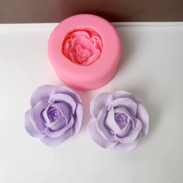
3D Rose Flower Silicone Mold 1383
This compact rose mold illustrates why detail filling and tear protection must be reviewed together. The uncured material must reach the layered petal texture. Later, the cured mold must release those thin features without concentrating force around one edge.
Although the overall form is not large, the inner flower geometry creates a more demanding release path than a simple open tray.
- Useful reference for recessed detail and layered surfaces
- Shows why thin edges need controlled demolding
- Supports discussion of flowability and local tear risk

Fairy Girl Relief Silicone Mold AA003
This relief format illustrates another selection challenge. Fine wings, flowers, hair, and background texture require reliable surface contact. Meanwhile, the broader rectangular body needs enough wall stability to maintain a flat and consistent casting profile.
The same geometry may be used with different casting materials, so finished-part rigidity and weight remain part of the material review.
- Useful reference for broad relief surfaces
- Shows the relationship between detail and wall support
- Supports candle, soap, plaster, and resin process planning
Scenario 1: Candle and Soap Molds
Candle and soap molds often combine decorative detail with flexible release. Fine lettering, petals, faces, and textured relief may benefit from a wall that opens without damaging the casting. At the same time, tall forms need enough support to resist bulging during filling.
A softer direction may help around narrow openings and projecting details. But a soft unsupported mold can lean or spread when the cavity is tall. A fitted holder or rigid shell can keep the outside profile stable while the inner wall remains flexible.
Flowability matters around embossed logos and fine texture. Even so, master preparation and air paths still control surface quality. A sample should include the actual wax or soap system, master finish, and planned release method.
Process temperature and compatibility should follow current technical information and representative testing. Pigments, fragrances, additives, coatings, and release products may change the result. For that reason, a broad application label should not replace validation under the intended process.
Scenario 2: Resin Molds
Resin molds often require a clean surface and controlled bubble release. Because many cured resin parts remain rigid, the silicone provides most of the movement during demolding. Deep reverse angles can therefore place significant strain around openings and planned cut lines.
Suitable flow helps reach engraved lines and narrow corners. Even so, silicone reproduces the master surface rather than improving it. Scratches, print layers, pinholes, contamination, and incomplete sealing may transfer directly into the mold cavity.
Compatibility should be checked with the actual resin system and master material. Pigments, fillers, coatings, release products, and partially cured surfaces may affect the result. A small contact test can identify problems before a full mold consumes substantial material.
Where the finished part remains mechanically locked, additional softness may not solve the problem. A revised parting line, removable core, or multi-part layout can reduce stress more effectively. These changes also protect thin features during repeated production.
Scenario 3: Gypsum, Plaster, and Concrete
Mineral casting materials add weight and handling demands. A filled mold can become difficult to move, while broad walls may spread under the wet load. This means the support method should be established before hardness is selected.
A flexible cavity can release stone-like texture and small reverse details. But a thin flange should not become the main lifting point. Hidden gripping areas can be widened or supported so the load spreads across a larger section.
The outer shell must also open in a practical direction. A rigid jacket that traps the cured casting creates another demolding problem. Parting lines, fasteners, registration points, and lifting access should follow the complete release sequence.
Cleaning becomes part of durability as well. Sharp scraping tools can create small cuts, while residue may affect detail and release. A useful sample program should therefore include cleaning and reuse rather than one fresh casting only.
Scenario 4: Large or Deep Molds
Large or deep molds reveal why low viscosity does not equal adequate structure. A fluid mixture may reach the bottom of a deep mold box and fill narrow spaces. After curing, the wall still has to resist liquid pressure, handling, and casting weight.
A tall liquid column can push soft walls outward. Greater cured firmness may help, but a well-fitted support shell often provides more direct control. This arrangement allows the inner mold to remain flexible where demolding requires movement.
Deep cavities also make air release more difficult. Bubbles must travel farther, while ledges and enclosed details create hidden pockets. Pour direction, vents, an initial detail layer, batch size, and available degassing equipment should all enter the process plan.
Large pours increase leak risk and working-time pressure. For that reason, mold-box sealing, secondary containment, mixing capacity, and transfer steps should be tested before scale-up. Staged pouring also requires a separate check of layer timing and interface condition.
Choose the Right Next Step for Your Project
Choose the path that matches what you are buying. Use a material review when the mold design already exists and the goal is to replace or approve the silicone. Use custom mold development when wall thickness, cuts, parting lines, support geometry, or the release route still need to be designed.
Custom Mold Development
A project-specific review is appropriate when wall thickness, undercuts, cut lines, or support geometry remain open. Material behavior and mold construction can then be assessed as one system rather than two separate purchases.
- Provide drawings, dimensions, and release direction.
- Identify the master and casting materials.
- Mark thin sections, reverse details, and planned openings.
- Describe production frequency and available support.
Material for Existing Tooling
An established mold design still requires a structured material check. Wall stability, opening size, damaged areas, casting weight, and the existing support shell should be documented before a replacement direction is approved.
- Record the current material and observed failure area.
- Confirm the actual casting and cleaning process.
- Photograph cuts, stretched lips, and unsupported walls.
- Run a controlled comparison before production use.
What to Check Before Approving Production Material
A useful material discussion begins with a project record rather than a request for the softest or thinnest grade. Geometry, casting material, support method, and expected production pattern should appear in the same inquiry. This information gives each published property a practical role.
The latest TDS and SDS should be reviewed before approval. In addition, any performance claim important to the application should be supported by an available test document or representative trial. Unconfirmed assumptions should not become production specifications.
Clarify How Each Property Was Tested
Ask whether the published viscosity refers to one component or the mixed material. Temperature and measurement conditions also matter. Likewise, Shore A readings should be interpreted with the stated cure condition and test timing.
Tear values require the test method, specimen type, and unit. If two data sheets use different methods, the numbers may not support a direct ranking. A side-by-side sample using the highest-risk mold feature may then provide more useful evidence.
Make the Sample Represent the Real Process
A flat cup sample may confirm that curing occurs, but it does not reproduce a deep undercut or heavy casting. The test should include the real master surface, casting material, release direction, and planned support method. It should also reproduce the smallest section or most difficult opening.
Production handling belongs in the trial as well. Mixing, degassing, pouring, demolding, cleaning, and storage can each influence the result. For that reason, approval should consider the complete cycle rather than surface appearance after one cure.
Six Material-Selection Red Flags
Most avoidable problems begin with incomplete project information. The following signs do not prove that a grade is unsuitable. But they identify where a design review, document check, or representative test is still missing.
No wall thickness, support plan, casting weight, or release path appears beside the Shore A request.
Leak control, vertical retention, batch size, and the available air-removal process remain undefined.
Different units or specimen methods are ranked as direct equivalents without supporting context.
A large or deep liquid load relies on the inner elastomer alone to maintain the cavity profile.
The master, casting system, coating, pigment, filler, or release process differs from production.
The latest documents, batch identity, cure observation, and agreed acceptance checks are not recorded.
Selection Worksheet
A structured worksheet prevents one attractive property from controlling the decision. It also creates a shared record for material review, sample planning, and production approval. Each field should use actual project information rather than a general application label.
Mold Geometry
- Overall dimensions, cavity depth, and cavity count
- Narrowest opening and deepest undercut
- Thin lips, stems, fins, and hidden notches
- Parting lines, planned cuts, inserts, and removable cores
Casting Material
- Exact material reference when available
- Pigments, fillers, powders, or aggregate
- Surface treatment or planned release process
- Expected cured rigidity and finished-part weight
Demolding
- Main release direction and opening distance
- Areas that must stretch, fold, or roll
- Grip points used during release
- Risk from sharp edges or mechanically locked features
Production Process
- Target production frequency and batch size
- Mixing, vacuum, pressure, or metering equipment
- Available mixing and pouring time
- Cleaning, storage, and inspection routine
Support Method
- Base board, holder, cradle, or mother mold
- Shell parting line and fastening method
- Registration and alignment features
- Lifting access and secondary containment
Sample Validation
- Cure check against the actual master
- Flow test in the smallest feature
- Demolding trial at the highest-risk area
- Repeat inspection after cleaning and reuse
Frequently Asked Questions
What Shore hardness is suitable for silicone mold making?
There is no universal Shore A value for silicone for mold making. A softer material may help release deep undercuts, while a firmer material may support broad walls more steadily. Geometry, wall thickness, casting weight, release distance, and external support should define the starting range. Confirm the final choice with the current TDS and a representative sample.
Is lower viscosity always better for detailed molds?
No. Lower viscosity can improve flow into texture and narrow spaces, but it can also increase leakage or drain from vertical surfaces. Detail quality also depends on master preparation, air paths, pour direction, working behavior, and batch size. A flow test should reproduce the real cavity depth and smallest feature.
Why is tear strength important for deep undercuts?
Deep undercuts force the mold to stretch around a restricted opening. Stress then gathers around cuts, thin edges, and narrow corners. Stronger tear resistance can slow crack growth, but it cannot remove mechanical locking. Severe geometry may still require a revised parting line, removable core, or multi-part structure.
How do hardness and support shells work together?
Hardness affects how firmly the inner mold resists deformation. A support shell holds the complete cavity in position during filling and curing. This means a flexible inner mold can pair with a rigid outer structure. The shell must fit accurately and separate along a practical release path.
Should a sample be requested before ordering production material?
A sample is advisable whenever geometry, compatibility, or production scale creates meaningful risk. The trial should include the actual master surface, casting system, release direction, support method, and highest-risk feature. Results should also be checked against the current TDS, SDS, and available test documentation.
Three Decisions Before You Place an Order
Before ordering production quantity, make three decisions in this order. This keeps the purchase tied to the real failure risk instead of one attractive data-sheet number.
- Choose the first material direction from the dominant risk: release movement, wall stability, filling, or edge damage.
- Confirm whether wall thickness and a holder or mother mold will carry the casting load instead of expecting the inner silicone to do everything.
- Approve the material only after the actual master, casting system, release path, and highest-risk feature have passed a representative trial.
Get a Project-Specific Silicone Recommendation
Send the conditions that determine the choice, and BKSilicone can help narrow the starting direction before you commit to production quantity. The goal is to identify what should be tested first—not to recommend a grade from an application name alone.
- Submit dimensions, drawings, and release direction.
- Identify the actual master and casting materials.
- Mark deep undercuts, thin edges, and planned cuts.
- Describe production frequency and support equipment.
For a project-specific review of silicone for mold making, include the master material, casting material, dimensions, deepest undercut, narrowest opening, planned cuts, support method, and expected production frequency.