
Large custom silicone molds cannot be designed by simply scaling up a smaller mold. As a part becomes deeper, wider, or heavier, the mold needs a clear plan for support, filling, opening, and demolding. For this project category, see the LargeForm 25–35CM production system.
For deep or complex parts, the flexible silicone, support shell, parting line, and release direction have to work together. The goal is practical: keep the cavity stable during casting and let the finished part come out without excessive stretching, damage, or awkward handling.
When a Mold Becomes a Large or Complex Project
No single dimension defines a large mold. Instead, complexity begins when size changes filling behavior, shape stability, release, or daily operation. A long shallow form may remain manageable, while a smaller sculptural part can become difficult because several undercuts pull in different directions.
Overall volume still affects material use, working weight, and handling space. However, cavity depth, unsupported wall height, broad flat areas, and narrow access points often create harder engineering questions. These conditions can change how the silicone seats inside its support structure.
Finished-part weight adds another layer. During production, the complete system may include the silicone body, casting material, support shell, flanges, clamps, and a handling frame. An assembly that feels manageable when empty may therefore need several operators or lifting assistance after filling.
The casting material also changes the project category. Wax, resin, plaster, and concrete place different loads on flexible walls and follow different release conditions. Geometry should be reviewed together with the intended casting process.
Available workspace matters just as much. A mold may fit on a table but leave no room for shell panels, flange opening, or part rotation. Doorways, nearby equipment, and ceiling height can also limit movement between production stages.
Signs a Standard Mold May Not Be Enough
- Deep cavities that restrict access during release.
- Wide walls or bases that may bow under load.
- Heavy castings that cannot be lifted from one side.
- Reverse angles, internal collars, or opposing undercuts.
- Fragile details near likely opening lines.
- Limited space for turning or storing shell sections.
- Repeated production that depends on accurate reassembly.
The best starting point is a complete cycle map. It should cover assembly, filling, curing, movement, shell removal, silicone release, part support, cleaning, and storage. Once that sequence is clear, structural decisions become easier to justify.
When Does a Large Part Need a Custom Mold?
A ready-made mold can work when its cavity already matches the required shape, size, casting material, and release method. A custom mold becomes the better choice when the part has its own dimensions, controlled visible surfaces, deep returns, substantial filled weight, or handling limits that a catalog mold cannot address.
Custom Project
Choose a custom route when the mold structure has to follow the actual part, casting process, or production space rather than a standard cavity.
- Unique geometry or a physical master.
- Restricted seam locations.
- Heavy casting material.
- Repeat production with controlled reassembly.
Ready-Made Mold
A ready-made option may be suitable for a common open shape when the cavity already matches the intended result and no dedicated support or seam planning is required.
- Standard shape and dimensions.
- Simple release path.
- Modest working weight.
- No dedicated support-shell requirement.
Why Flexible Silicone Needs External Support
Silicone flexibility helps detailed surfaces and some undercuts release without rigid tooling. At the same time, it allows large walls and broad bases to bend. An external support shell, often called a mother mold, holds the flexible mold in its intended working position.
The shell does not replace the detail-forming surface. Instead, the silicone reproduces the part geometry, while the external structure controls the overall shape during filling and curing. This division becomes important when gravity or casting pressure can move unsupported areas.
Support should follow loaded regions rather than surround the mold loosely. Tall walls, deep cavities, wide spans, and projecting sections may need close seating. Otherwise, local bulging can occur even when the shell appears rigid.
Even contact matters as much as stiffness. A hard pressure point can push the silicone inward, while a gap can allow the wall to move outward. The shell should create defined support surfaces instead of relying on random contact.
Assembly and removal must remain practical. A one-piece shell may work around an open form, yet it can trap a wrapped or deeply recessed mold. In those cases, two-piece or multi-piece shell sections can create a controlled removal sequence.
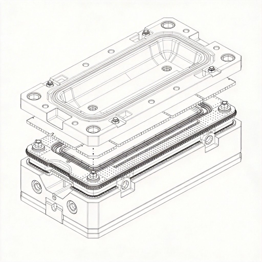
This structure reference helps explain why a large silicone section may need external support during filling, curing, opening and storage.
Review Custom Mold DevelopmentWhat a Support Shell Should Do
Material choice and shell thickness depend on geometry, expected loads, cleaning methods, and available fabrication equipment. Because every project is different, shell material and thickness should be confirmed for the actual geometry, casting load, cleaning method, and handling setup.
Parting Line Strategy
A parting line defines where the mold opens and where separate sections meet. Its position affects demolding, seam visibility, sealing, shell design, and assembly time. Because these effects remain connected, the most hidden line is not always the most workable line.
A single-piece mold can suit open geometry with one clear release direction. It reduces assembly steps and avoids a main seam. However, deep cavities or strong returns can demand too much silicone stretching.
A two-piece mold often works when the part has a natural front and back, or when one main seam can avoid critical detail. Both halves still need reliable registration and accessible flanges.
A multi-part mold adds sections or inserts around locked features. It can reduce concentrated release force and protect fragile areas. The trade-off is more sealing, cleaning, labeling, and reassembly work.
Where Should the Parting Line Go?
A seam may leave a fine witness line on the casting. Depending on the application, that mark may remain acceptable, require finishing, or be prohibited on a visible face. Surface priorities should therefore be ranked before the line is approved.
Natural edges, corners, texture changes, or hidden back surfaces often provide useful locations. However, a line inside a deep decorative recess may be difficult to clean and align. A more visible but accessible line can produce a more reliable result.
Every section also needs enough flange area for sealing, registration, handling, and controlled separation. The shell divisions must support the same opening sequence. If the shell moves one way while the silicone must release another way, the design can become blocked.
A reliable strategy answers four questions: which section opens first, what stabilizes the remaining sections, where each section can be gripped, and how every part returns to the same position. If any of those steps is unclear, the mold may be difficult to use in daily production.
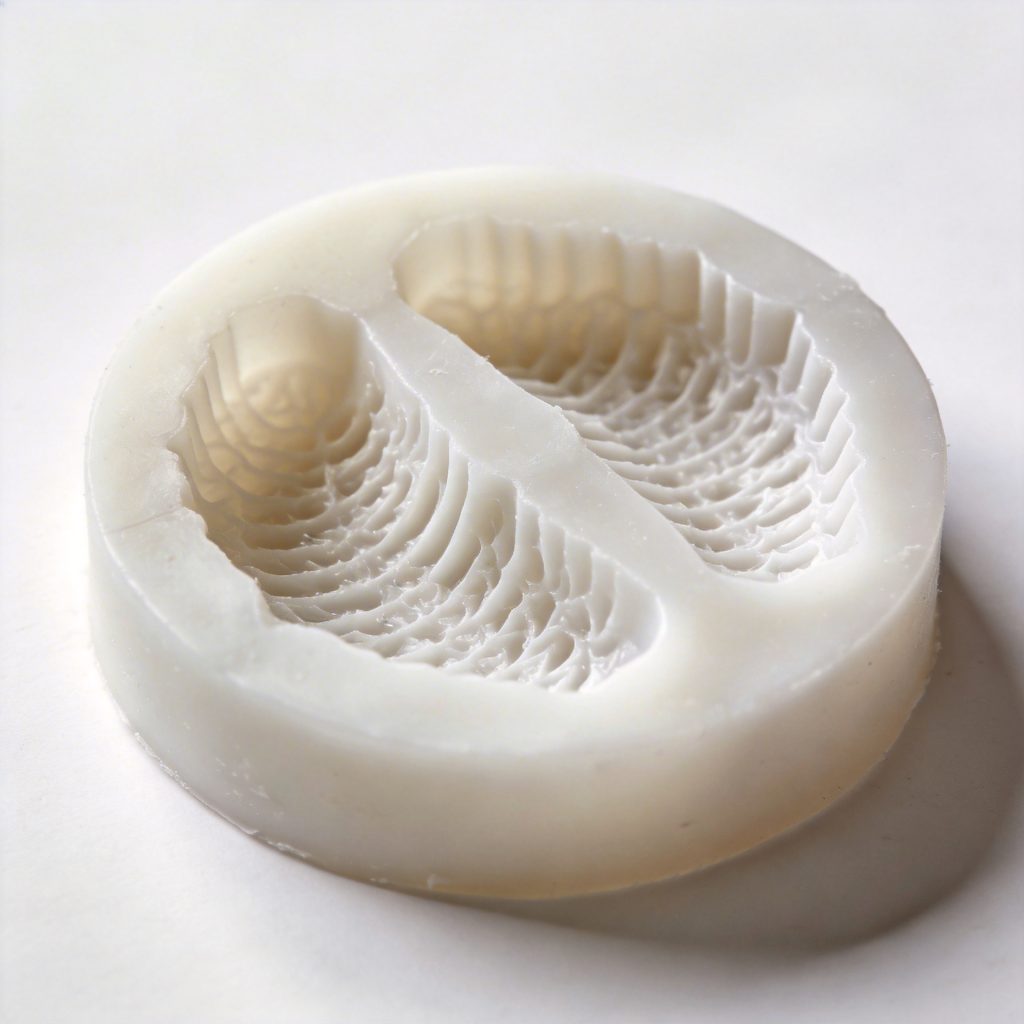
Visible faces, fragile details and access for opening should be considered together instead of choosing a seam only because it is hidden.
See Silicone Mold Design BasicsDemolding Direction and Undercuts
Demolding direction describes how the finished part leaves the cavity. Simple forms may release through one straight movement, while complex parts may need peeling, rotation, insert removal, or staged opening. The review should begin from the finished casting rather than the empty mold.
Each projection, recess, opening, lip, and return should be checked along the planned release path. An undercut exists whenever a feature resists that movement. Some undercuts can release through controlled flexing, but others create a mechanical lock.
Depth increases the risk because deeper walls create more surface contact and less access. Long channels can also trap silicone around delicate cast features. Even when the mold survives, the finished part may chip or distort before release is complete.
Thin edges need special care. Pulling directly against a narrow rim concentrates force, so the casting may need support while the silicone peels away. Closed cavities can also create suction and increase apparent release force.
Features That Often Cause Demolding Problems
- Reverse angles behind a projection.
- Deep grooves with narrow openings.
- Internal lips, collars, or wrapped features.
- Long cores with limited withdrawal space.
- Opposing undercuts with different release directions.
- Fragile edges near the main opening line.
A removable insert can solve a local lock before the main mold opens. However, that insert needs its own registration, grip point, and storage position. Without those details, the solution creates another operating problem.
Release agents may support compatible material systems, but they cannot correct locked geometry. Their use should follow current TDS or SDS information and sample testing. Mechanical release must still come from the mold structure.
Handling Weight and Operator Safety
Large mold planning must consider weight throughout the full cycle. The empty silicone body represents only one condition, while the filled assembly may include casting material, shell panels, clamps, frames, and temporary supports. Base handling decisions on the heaviest stage of the production cycle.
Filled weight affects table loading, turning effort, shell stability, and flange stress. It can also shift the center of gravity while material enters the cavity. An uneven form may load one side much earlier than the other.
A stable base can reduce this risk, although it must not block shell joints or opening flanges. Some projects also fill in one orientation and release in another. In that case, controlled rotation may need defined contact surfaces, a frame, or suitable lifting equipment.
Grip locations should avoid flexible silicone whenever possible. Direct lifting can stretch thin walls or tear edges. Movement may therefore need to occur through the shell, base, frame, or another dedicated support point.
How the Mold Stays Aligned During Casting
Wall support controls shape during filling, while flanges create mating surfaces between mold sections. Registration features help those sections return to the same location after opening. Failure in one area can therefore affect the others.
Large vertical walls may move outward under pressure, while broad bases can sag under material weight. The shell should support the intended cavity shape without creating local pressure marks.
Flanges provide space for alignment, sealing, clamping, and controlled separation. They must remain accessible after the shell is installed. A hidden or narrow flange can make daily opening difficult.
Registration features reduce sliding and reveal incorrect assembly. However, their geometry should not create fresh locking points. They should also remain easy to inspect and clean.
Large molds often need local and overall registration. A small key can align nearby edges, while broad support surfaces control the complete assembly. Together, these features reduce steps across the parting line.
Casting Material Changes the Design
The same cavity may need different support and release planning for different materials. Density, flow behavior, cure conditions, surface adhesion, and handling method all influence the structure. Identify the casting material before the mold structure is finalized.
Formulations vary within every material family. Current TDS and SDS documents should guide compatibility, working conditions, cleaning, and safety decisions. When available records do not confirm the combination, sample testing should come before full-scale production.
Wax
Wax can reproduce fine detail, depending on formulation and working condition. However, temperature and cooling behavior may affect support and release timing. Large wax castings can also remain vulnerable to distortion during early handling.
Resin
Resin systems differ in viscosity, cure behavior, heat generation, and adhesion. A large pour may create sustained wall pressure while the material remains fluid. Deep sections may also need suitable filling direction and venting.
Plaster and Similar Mineral Mixtures
Plaster-based materials can load broad walls and bases during filling. Large parts may remain fragile before they support their own weight. This may require a defined order for shell removal, silicone peeling, and part support.
Concrete and Cement-Based Mixtures
Concrete and cement-based mixtures can create substantial working weight. Aggregate, reinforcement, vibration, and placement method may add further conditions. Wall support, base stability, surface reproduction, and cleaning access all need review.
Questions to Ask Before Finalizing the Mold
- What is the material condition during filling?
- How much load can develop against flexible walls?
- Does the process involve heat, vibration, vacuum, or pressure?
- Can material enter flange gaps or registration areas?
- When can the finished part support its own weight?
- What cleaning method follows each cycle?
Changing the casting material after design approval can require structural changes. A mold prepared for a light material may not support a denser mixture. If several materials will use the same cavity, each process should receive a separate review.
What to Check in the First Trial Cast
The first trial cast shows whether the mold works as expected under real production conditions. A digital review can identify obvious risks, but it cannot fully predict wall movement, leakage, release effort, or how easily operators can reach each section.
Assembly order, shell installation, filling orientation, table setup, and demolding direction should match the planned process. Clear notes and photos make later changes easier to evaluate.
Shape stability should be checked before and after filling. Reference points can reveal whether broad walls moved under load, while wrinkles or bulges may indicate gaps between the silicone and shell.
Leakage should be traced to its source rather than covered with extra clamping. Parting surfaces, flange edges, insert boundaries, and shell joints all need inspection. Parting-line appearance and registration accuracy should also be recorded.
Demolding force should remain controlled through the planned sequence. Sudden pulling, uncontrolled twisting, or extreme stretching suggests that the release path needs revision. The casting should remain supported until fragile features are clear.
What to Send When Requesting a Quote
A useful quotation request needs more than an overall length and a reference image. The supplier also needs to understand the complete geometry, casting material, expected weight, release limits, and the space available for filling and demolding.
A three-dimensional model or dimensioned drawing should represent the real finished part, including back surfaces, openings, recesses, and known undercuts. Missing geometry can change the proposed parting line or number of sections.
Overall dimensions should include the complete part envelope and maximum cavity depth. Strict visible areas and restricted seam locations should also be marked. That information helps position parting lines away from critical surfaces where possible.
Finished-part weight should be supplied when known. If it remains uncertain, material density and estimated volume can support an early review. Final handling decisions may still require confirmed data.
The casting material should be identified as specifically as possible. A general label such as “resin” may not reveal relevant working conditions. Current TDS, SDS, or existing test records can provide essential context.
Available production space should include table size, side access, turning room, shell storage, ceiling height, and transport paths. Existing lifting equipment, carts, frames, vacuum systems, or vibration equipment should also be documented.
Packaging and transport limits can influence shell breakdown and section weight. Door widths, crate dimensions, storage orientation, and movement between facilities should be stated before the structure becomes final.
When a physical master exists, its condition should be documented. Surface damage, repairs, flexible areas, or incomplete details can transfer into the mold. The RFQ should also state which decisions remain open, such as parting-line placement or shell breakdown.
Common Design Mistakes
Large mold problems often begin with a reasonable idea applied at the wrong scale or in the wrong sequence. The following red flags do not automatically make a project impossible. However, each one should trigger a documented review.
Scaling Up a Small Mold
Pressure, self-weight, and release effort do not increase in a simple visual proportion. A thin wall that works at small scale may bow when enlarged.
Ignoring the Support Shell
Flexible walls may change shape during filling. Adding support later can also block flanges and registration areas.
Unworkable Parting Lines
A line may look clean in a model yet remain inaccessible on the production table. Shell panels or nearby equipment can block opening.
No Handling Plan
An empty mold may feel manageable, while the filled assembly becomes difficult to turn. Grip points and resting positions need early planning.
Too Many Loose Sections
Extra inserts reduce some locks but increase sealing, labeling, and cleaning work. Every section should solve a defined problem.
Skipping a Representative Trial
Small tests may confirm compatibility but not full-scale deformation. Structural risks need a trial that reflects the real process.
Frequently Asked Questions
When does a large silicone mold need a support shell?
A support shell becomes important when the flexible mold cannot hold its intended shape during filling, curing, movement, or storage. Common warning signs include tall walls, broad spans, deep cavities, heavy material, and visible movement under light handling.
However, overall size alone does not decide the issue. Geometry, loaded weight, casting orientation, and trial evidence should guide the final support plan.
How is the parting line selected for a complex mold?
The line should balance release direction, seam visibility, flange access, sealing, and repeatable assembly. Natural edges or hidden surfaces can help, yet an accessible line is often better than one that cannot be opened safely.
Each section should have a clear movement and grip location. A digital review and representative trial can then confirm the choice.
When is a multi-part silicone mold necessary?
A multi-part structure becomes useful when different features cannot release through the same direction. Deep returns, wrapped geometry, internal lips, isolated undercuts, and fragile projections often create that condition.
Still, every section should solve a specific problem. Registration, sealing, removal access, cleaning, and storage should be defined before approval.
What information is needed to evaluate demolding risk?
The review needs complete geometry, cavity depth, undercut locations, fragile edges, casting material, expected part weight, and available release space. Planned orientation and restricted surface areas also matter.
Current TDS and SDS information may be needed for the casting material and any release treatment. When uncertainty remains, sample testing should confirm the proposed method.
How should a quotation request for a large mold be prepared?
The request should include a model or drawing, overall dimensions, expected part weight, casting material, workspace, available equipment, target production volume, and known demolding limits.
Restricted seam locations, packaging limits, doorway sizes, and handling conditions should also be stated. Complete data allows the support shell, parting line, section layout, and trial plan to be reviewed together.
Planning a Large or Complex Silicone Mold?
Send the part file or sample details together with the casting material, expected size, weight, and any restrictions on seams or demolding. This gives the project team enough context to discuss a practical mold structure before quotation.
If some details are still uncertain, mark them clearly. They can be reviewed before the parting line, support shell, or section layout is confirmed.
- Three-dimensional file, drawing, or physical-master details.
- Overall dimensions and expected finished-part weight.
- Casting material and available TDS or SDS documents.
- Production space, equipment, and operator limits.
- Surface, seam, transport, and demolding restrictions.